Aivia Software
3D Crop
The 3D Crop tool lets you add, remove, and adjust cube-shaped region boundaries in an image; these cubes may be used for cropping the image, used as regions of interest (ROIs) when applying or previewing recipes, or zoomed to in the Image Viewer. There are options to lock the positions of designated cubes and to translate cubes only along specific axial directions.
Interface
The 3D Crop tool is one of eight tools found in the 3D Tools tab in the (Pre-version 12) Analysis Panel. Go to 3D View or 3D Plane View to show the 3D Tools tab. Click on the 3D Tools tab, and click on the 3D Crop icon  to launch the tool. When the 3D Crop tool is first launched in 3D View, the GUI below appears, and a cube named "User Defined 1" is placed in the center of the image.
|
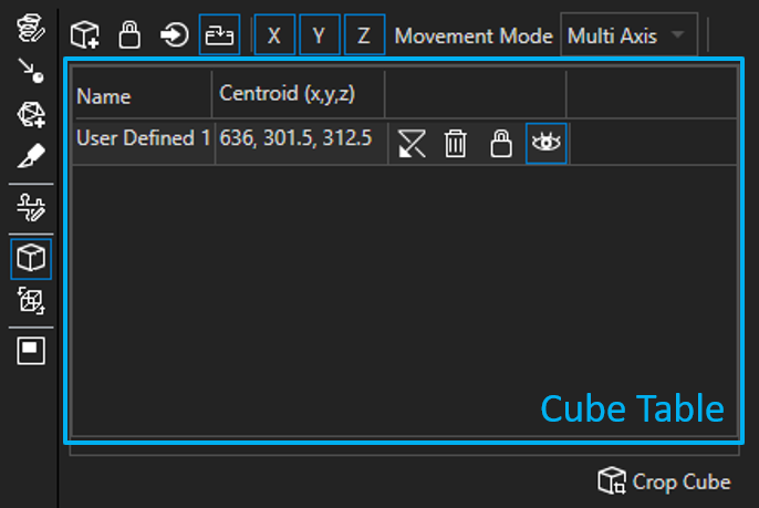
| 3D Crop GUI |
Tool options and functions
The 3D Crop options and functions, which are found above and below the Cube Table, are described in the following table:
| Name | Icon | Description |
|---|---|---|
| Add Cube |
| Adds a new cube to the image |
| Un/Lock Cube Movement |
| Allows/Restricts changes in the size and position of the selected cube |
| Zoom to Cube |
| Zooms to the selected cube, centering it in the Image Viewer (in 3D View) or 3D pane (in 3D Plane View) |
| Show Cube Labels |
| Toggles the display of cube names in the Image Viewer |
| Allow/Restrict Movement in X |
| Allows/Restricts translation of any cube in the x-direction |
| Allow/Restrict Movement in Y |
| Allows/Restricts translation of any cube in the y-direction |
| Allow/Restrict Movement in Z |
| Allows/Restricts translation of any cube in the z-direction |
| Select Movement Mode |
| Allows selection of Movement Modes that restrict translation of any cube accordingly
|
| Crop Cube |
| Crops out the selected cube, generating a new image that is added to the Image Explorer and displayed in the Image Viewer once it has been created |

Cube Table
The Cube Table is labeled and outlined in light blue in the "3D Crop GUI" image. Each cube has its own row in the Cube Table. The name of each cube and the coordinates of its centroid (in pixels) are displayed. There are also options to revert the position of, remove, allow/restrict changes in size/position to, and hide/show each cube.
Options for individual cubes
| Option | Icon | Description |
|---|---|---|
| Revert Cube |
| Reverts the cube to its initial, automatically generated size and position |
| Remove Cube |
| Removes the cube |
| Un/Lock Cube Movement |
| Toggles a restriction on any change in the size or position of the cube |
| Un/Hide Cube |
| Toggles on/off the display of the cube in the Image Viewer |

Using 3D Crop
To launch the 3D Crop tool, click on the 3D Tools tab in the Analysis Panel in Aivia, and then select the 3D Crop tool from the 3D Tools toolbar. This will open the 3D Crop interface. When the 3D Crop tool is launched for the first time, an automatically generated and centrally located cube named "User Defined 1" is shown.
Add a cube
Click the Add Cube icon  to add a new cube. New cubes are named "Box Region X" by default, where instead of 'X' there is the lowest positive number that yields a non-duplicate cube name.
Add a cube via the Recipe Console
A cube may also be added by going to the Recipe Console tab in the Analysis Panel, clicking the Expand icon ![]() next to Input and Output in any recipe, clicking the Expand icon
next to Input and Output in any recipe, clicking the Expand icon ![]() next to Regions of Interest, and then clicking the Add Box ROI icon . Double-click the name of any cube in the Regions of Interest section to enable editing of the cube's name. Any cube/box ROIs shown in the Regions of Interest section will also appear in the Cube Table in the 3D Crop tool interface.
next to Regions of Interest, and then clicking the Add Box ROI icon . Double-click the name of any cube in the Regions of Interest section to enable editing of the cube's name. Any cube/box ROIs shown in the Regions of Interest section will also appear in the Cube Table in the 3D Crop tool interface.
On this page:
Select a cube
Select a cube by clicking on it in the Image Viewer or by clicking on its row in the Cube Table.
Change the size/position of a cube
To change the position of a cube without changing its size, select the cube, and then click and drag the red sphere that is in the center of the cube. Click and drag any of the other red spheres to change the extent of the cube along one direction; dragging any of the non-central red spheres changes the size AND centroid location of the cube. To change the size of a cube in all three dimensions without changing its centroid location, hold Ctrl and right-click and hold within the cube boundary, pull the mouse toward or away from the center of the cube, and release the mouse button when the cube is the desired size.
Un/Lock cube movement
Un/Lock changes in size and position for a cube by either clicking on the Un/Lock Cube Movement icon  in its row of the Cube Table or by selecting the cube and clicking the Un/Lock Cube Movement icon in the Tool Options and Functions section. Movement is locked for a cube if the Un/Lock Cube Movement icon in its row of the Cube Table is outlined in blue. None of the red spheres may be clicked and dragged for a locked cube nor can the size of the cube be changed by
 Ctrl + right-clicking and dragging.
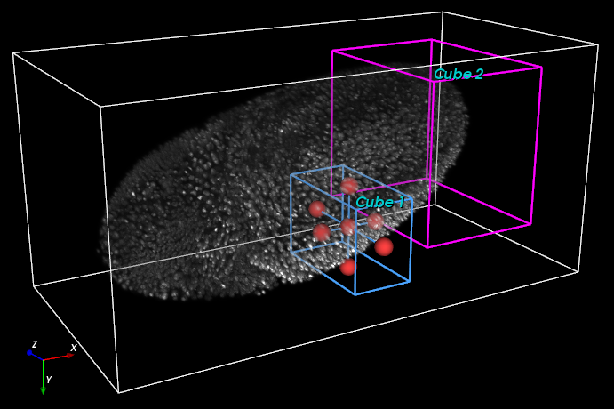 |
| Image with two cubes and "Cube 1" selected |
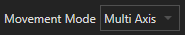
Change the Movement Mode
There are options to allow translation of cubes only along designated axial directions. Single Axis, Multi Axis, or Longest Axis mode may be selected from the Select Movement Mode drop-down menu. The directions along which translation is allowed are outlined in blue; for example,  indicates that translation in the x- and y-directions is allowed, but translation in the z-direction is locked. Note that Movement Modes only un/lock changes in position and NOT size, so the centroid of a cube may still be moved along a locked direction if the size/extent of the cube along the locked direction is changed.
Single Axis
To enter the Single Axis Movement Mode, select Single Axis from the Select Movement Mode drop-down menu. All cubes may only be translated in one axial direction in this mode. Click on the Allow/Restrict Movement icon for the desired axis of translation ( ,
,  , or
, or  ) to set it as the unlocked axis.
Multi Axis
Multi Axis is the default Movement Mode, but it may also be chosen by selecting Multi Axis from the Select Movement Mode drop-down menu. Toggle the Allow/Restrict Movement icons (, , or ) to un/lock movement along any combination of axial directions, though movement along at least one direction must be allowed.
Longest Axis
To enter the Longest Axis Movement Mode, select Longest Axis from the Select Movement Mode drop-down menu. Cubes may be translated in any axial direction in Longest Axis mode but only along one axial direction at a time: as the central red sphere of a cube is dragged, the cube is translated in the axial direction closest to the direction that the mouse is dragged.
Revert a cube
Click on the Revert Cube icon  in a cube's row of the Cube Table to return the cube to its initial, automatically generated size and position.
Revert a cube via the Recipe Console
The Revert Cube option is also available in the Regions of Interest table in the Recipe Console tab of the Analysis Panel. To show the Regions of Interest table, click on the Recipe Console tab in the Analysis Panel, then the Expand icon ![]() next to Input and Output in any recipe, and then the Expand icon
next to Input and Output in any recipe, and then the Expand icon ![]() next to Regions of Interest.
next to Regions of Interest.
Remove a cube
Click the Remove Cube icon  in a cube's row of the Cube Table to remove the cube.
Remove a cube via the Recipe Console
The Remove Cube option is also available in the Regions of Interest table in the Recipe Console tab of the Analysis Panel. To show the Regions of Interest table, click on the Recipe Console tab in the Analysis Panel, then the Expand icon ![]() next to Input and Output in any recipe, and then the Expand icon
next to Input and Output in any recipe, and then the Expand icon ![]() next to Regions of Interest.
next to Regions of Interest.
Un/Hide a cube
Click the Un/Hide Cube icon  in a cube's row of the Cube Table to hide or show that cube.
Un/Hide cubes via the Recipe Console
Cubes may also be shown and hidden (as a group, not individually) from the Regions of Interest table in the Recipe Console tab of the Analysis Panel. To un/hide cubes by way of the Recipe Console, click on the Recipe Console tab in the Analysis Panel, then on the Expand icon ![]() next to Input and Output in any recipe, and then on the Show ROIs icon (
next to Input and Output in any recipe, and then on the Show ROIs icon ( or
or  ) next to Regions of Interest.
Show/Hide cube labels
Click on Show Cube Labels icon  to toggle on/off the display of cube names in the Image Viewer.
Zoom to a cube
Select a cube, and then click the Zoom to Cube icon  to zoom to the selected cube in the Image Viewer (if in 3D View) or in the 3D pane (if in 3D Plane View).
Crop out a cube
Select a cube, and then click the Crop Cube button at the bottom of the interface to generate a new image that contains only the image data lying within the selected cube. This cropped image is displayed in the Image Viewer and has a thumbnail that appears in the Image Explorer once it has been generated, but the cropped image is NOT automatically saved.
Image credits
Philipp Keller, Howard Hughes Medical Institute, Janelia Farms Research Campus, Ashburn VA; Cell Tracking Challenge, http://www.celltrackingchallenge.net/datasets.html
Related articles