Clipping planes and ortho planes in Display settings provide The Clipping & Ortho Planes section provides tools that let you clip, or hide, a portion portions of the display displayed volume. This tool is These tools are especially useful for visualizing the interior regions of datasets that are too opaque to visualize in normal 3D display mode.
Interface
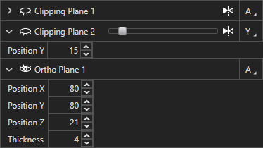
The clipping planes and ortho planes Clipping & Ortho Planes tool is found in the Display settings panel in Aivia below the in 3D Display Options panel. The table header contains controls for adding or , removing, and resetting planes as well as toggling and setting the color of Clipping Caps. Each clipping/ortho plane has its own table row represents a single instance of the clipping plane or ortho slice with tools and options that are applied to the specified instancefor the specific plane. An example of the clipping plane display Clipping & Ortho Planes table is shown below:.

| Panel | |
|---|---|
On this page:
|

Table header
The table header contains descriptions for each column on in the display table as well as global options for adding and removing the planes. The four (4) buttons are:, removing, and resetting planes as well as toggling and setting the color of Clipping Caps. The buttons in the table header are described in the table below.
| Name | Icon | Description |
|---|---|---|
| Add new clipping planeClipping Plane |
| Adds a new clipping plane to the display |
| Add new ortho slicerOrtho Plane |
| Adds a new ortho slice plane to the display |
| Reset plane positionPlane Position |
| Resets the position of the selected plane back to the center of the scene |
| Delete selected planeSelected Plane |  | Removes the selected plane from the display |
| Delete All Planes |
| Removes all planes from the display |
| Toggle Clipping Caps |
| Toggles the display of Clipping Caps, which are colored areas where mesh interiors intersect the plane Clipping Caps cannot be used with transparent meshes. |
| Set Clipping Caps Color |
| Opens a color picker from which the color of the Clipping Caps can be selected |


Table row
Each table row represents a single clipping/ortho plane or ortho slice on the display displayed image has a table row. Options in each row (see the table below) can be used to independently control the behavior of each clipping/ortho plane. The effects of the clipping plane is planes are cumulative when the multiple planes are toggled on. Each row can be controlled independently to customize the behavior for each clipping plane or ortho slice. There are six (6) controls:
| Name | Icon | Description |
|---|---|---|
| Show expanded optionsExpanded Options |
| Shows expanded clipping plane options for precise positioning of the clipping plane |
| Show/hide clipping planeHide Clipping Plane |
| Toggles the display of the clipping plane; when the clipping plane is hidden, it will is not be used for clipping away portions of the displayed scene |
| Flip clipping planeClipping Plane |
| Flips the face that which side of the clipping plane is shown and which side is clipped away in the display |
| Plane orientationOrientation |
| Specifies the translation axis for the selected clipping plane, ; there are four (4) options:
|
| Toggle volume clippingVolume Clipping |  | Toggles clipping of the volume rendering (i.e. channel display) by the specified plane |
| Toggle mesh clippingMesh Clipping |  | Toggles clipping of the mesh/surface rendering (i.e. objects) by the specified plane |


Additionally, a slider is provided on in each table row that lets you adjust the relative position of the clipping/ortho plane or ortho slice along the specified axis.
On-
screenview control
Each clipping plane and ortho slicer also contains an on-screen /ortho plane can be adjusted in the Image Viewer with a control widget that lets you move the clipping plane along the specified axis. When you mouse over the control, it will become highlighted in The clipping/ortho plane must be selected in the Clipping & Ortho Planes table for its widget to be shown. The row of the selected plane is blue in the table, and the selected plane has a red border in the Image Viewer. Deselect a plane in the Clipping & Ortho Planes table to hide its widget and border. Basic Widgets with one (1) control are available for planes with the Plane Orientation set as X, Y, or Z, and Advanced Widgets with nine (9) controls are available for planes with the Plane Orientation set as Advanced. When you mouse over a widget control, it turns white to indicate the selected control. There are two (2) different control widgets - basic and advanced, which are shown below (click to expand):
Basic
widget
| Expand | ||
|---|---|---|
| ||
|

The red arrow is always orthogonal to the clipping plane (i.e. pointing away from the plane) and is used for translating the clipping plane along the 3D volume.
The widget is accompanied by a red boundary along the edge of the 3D display to indicate the position of the clipping plane on screen. To hide the display of the widget and the plane, click on the table row to de-select it.
Using the clipping planeWidget
The Basic Widget allows you to translate the clipping/ortho plane along the axis that is orthogonal to the plane, which is the same as the axis indicated in the Axis column of the Clipping & Ortho Planes table for the selected clipping/ortho plane.
 |
| Basic Widget |
Advanced Widget
The Advanced Widget allows you to set the position and orientation of the clipping/ortho plane when its Plane Orientation is set as Advanced.
|
| Advanced Widget |

Using clipping and ortho planes
To add a clipping plane, click on the Add new clipping plane Clipping Plane icon  icon on in the table header. The clipping plane will be is added to the display with portions of the scene clipped away (see right, click to enlarge).
To add an ortho plane, click on the Add Ortho Plane icon  .
.
Adjust plane position
To adjust If the position Plane Orientation of the clipping/ortho plane , left click and drag red arrow on screen to move the plane along the axis of the red arrow.
Alternately, you can also adjust the position by left click and dragging the slider on the table row of the selected clipping plane to position the plane.

For precise positioning of the clipping plane at a known voxel location, you can expand the table row by clicking on the Expand  icon to show the Position textbox. Enter the plane position value into the textbox and press
 Enter to confirm.
is set as X, Y, or Z, the position of the clipping/ortho plane can be adjusted using the on-view Basic Widget, slider in the plane's table row, or Position textbox in the expanded plane options.
If the Plane Orientation of the clipping/ortho plane is set as Advanced, the position of the clipping/ortho plane can be adjusted using the on-view Advanced Widget or Position textboxes in the expanded plane options. There is no slider in the plane's table row when the Plane Orientation is Advanced.
Ortho-plane thickness can be adjusted using the Thickness textbox in the expanded plane options.
Toggle mesh and volume clipping
You can toggle clipping of the displayed channel, objects, or both by clicking on the
VolumeVolume icon
and/or Mesh icon
in the table row of the clipping
plane. The clipped display is indicated by a blue box surrounding the icons. All volume and/or mesh are clipped by the specified clipping plane./ortho plane. A comparison of the
displayclipping modes
areis shown below:
|
|
|
| Volume clipping only (objects off) | Mesh clipping only | Volume and mesh clipping |


You can specify different display types (volume or mesh) to clip the clipping mode for each clipping/ortho plane independently to customize the display of the clipped scene in the 3D viewView.
|
| Example of a clipped volume |

Flip display clipping
You can specify which face the side of a clipping plane clips to clip away by clicking on the Flip  icon to toggle which side of the clipping plane to remove from the displayFlip Clipping Plane icon
  . A blue bounding box surrounding the Flip Clipping Plane icon on in the table row indicates that the clipping plane is flipped from its default orientation.By By default, the clipping plane hides the portion of the image that is closer to the image origin (0,0,0) and progressively hiding those further away. When flip is toggled, the clipping plane will preserve the display that is closer to the origin and progressively hiding as the plane approaches the origin.See see the figures to the right for a comparison between flipped and unflipped clipping display.The orientation of the on-screen controls are also flipped when flip is enabled so that it is possible to manipulate the clipping plane controlsnon-flipped clipping displays).
 |
| Flip not enabled |
 |
| Flip enabled |
Toggle Clipping Caps
You can toggle Clipping Caps using the Toggle Clipping Caps icon  to fill the regions where meshes intersect the clipping/ortho plane with a solid color (see the figure to the right). You can specify the color of the Clipping Caps by clicking on the Set Clipping Caps Color icon
  and then selecting the desired color from the color picker. You may not show Clipping Caps while any meshes have greater than 0% transparency.
|
| Clipping Caps shown in orange |

Related articles
| Filter by label (Content by label) | ||||||||||||||||||
|---|---|---|---|---|---|---|---|---|---|---|---|---|---|---|---|---|---|---|
|
| Page Properties | ||
|---|---|---|
| ||
|