Aivia Software
Channel Settings
Channel Settings is one (1) of the four (4) display settings sections. This section lets you adjust the appearance of each channel on the currently displayed image. The adjustments applied here only change how the image is shown in the Image Viewer and do not change the underlying data on the image.
Interface
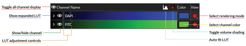
The Channel Settings panel is at the top of the column to the right of the Image Viewer by default. The Channel Settings table header contains controls that apply to the whole image, and each table row contains controls that apply to just the corresponding channel. An example of the Channel Settings table is shown below.
On this page:
Table header
The table header contains labels for each column as well as global display options for the image. The three (3) buttons in the table header are the following:
| Name | Icon | Description |
|---|---|---|
| Show/Hide All Channels |
| Toggles the visibility of all channels on the image |
| Auto-fit LUT |
| Toggles auto-fitting of the lookup table (LUT) function to the actual dynamic range of the image and updates the range for each frame |
| Toggle Volume Shading |
| Applies shading to the displayed volume in 3D View when Composite Volume mode is selected |

Table row
Each table row in the Channel Settings table represents a single channel on the displayed image. The background color of each row corresponds to the specified channel color in the Color column of the table. Each row can be controlled independently to adjust the display settings of each channel. There are five (5) controls:
| Name | Icon | Description |
|---|---|---|
| Show Expanded LUT |
| Expands the LUT display of the selected channel |
| Show/Hide Channel |
| Allows you to show or hide the selected channel from view |
| LUT Adjustment Controls |
| Allows you to specify the displayed dynamic range of the selected channel; there are two sliders that can be dragged along the entire table row:
|
| Color Picker |
| Opens a color picker that lets you select a desired display color for the selected channel |
| Render Mode Selector |
| Lets you specify the rendering mode of the selected channel in 3D View |


Using the Channel Settings panel
The Channel Settings are active whenever you have an image loaded and displayed in Aivia. The software automatically populates the table based on the number of channels that are on the image and the channel color(s).
Set channel visibility
Channels can be shown and hidden individually with the Show/Hide Channel icons to the left of their names. The Show/Hide Channel icon has two states:
| Display State | Icon | Description |
|---|---|---|
| Shown |
| The selected item is visible; click on the icon to hide the selected item. |
| Hidden |
| The selected item is not visible; click on the icon to show the selected item. |

Additionally, you can show/hide all channels by clicking on the Show/Hide All Channels icon in the table header.
Change render mode
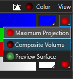
You can specify the rendering mode for channels in 3D View by clicking on the icon in the View column. Clicking on the icon will bring up a list of render mode options that are available for the selected item. There are three (3) options:
| Rendering Mode | Icon | Description |
|---|---|---|
| Maximum Projection |
| Sets rendering to Maximum Intensity Projection mode |
| Composite Volume |  | Sets rendering to Composite Volume mode |
| Preview Surface |
| Sets rendering to Preview Surface mode |


Once a new rendering mode is selected, the displayed image refreshes automatically to reflect the new selection.
Depending on your hardware, the size of the image and the rendering mode chosen, it may take Aivia up to several minutes to fully render the image with the specified settings.
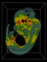
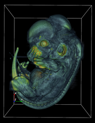
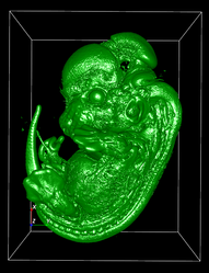
A comparison between the three (3) rendering modes is shown below.
|
|
|
| Maximum Projection | Composite Volume | Preview Surface |
|
| Render mode options |
Change channel color
You can change the channel color display by clicking on the icon (or colored rectangle) associated with the selected channel in the Color column. Clicking on the icon brings up a color picker menu, which allows you to specify a color.
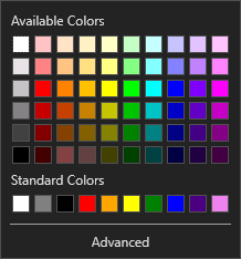
The Basic Color Picker (see right) is the default color picker, which presents a number of standard colors to choose from.
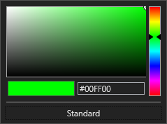
When you click on the Advanced button on the Basic Color Picker, the Advanced Color Picker will be shown (see right). Click or drag the slider on the right to specify the desired hue (color) and click anywhere on the main display to specify the saturation and brightness desired. Alternately, you can specify a color by entering the hexadecimal color code in the textbox below the main display.
Additional LUT mapping and color options are available in the Advanced Coloring menu, which is found in the right-click menu of each channel-name cell in the Channel Settings table. The Advanced Coloring > LUT Mappings menu contains a variety of LUT mappings that you may choose from.
|
| Basic Color Picker |
|
| Advanced Color Picker |
Change display brightness
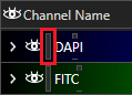
You can adjust the displayed brightness of channels using the lookup table (LUT) function built into the Channel Settings. An LUT control is circled in red to the right. There is one (1) pair of controls for each channel. When you hover over a control, the cursor changes into a left-right arrow, and you can click and drag the control to the left or right to modify the displayed dynamic range. This action does not alter the pixel/voxel values on the image, merely the brightness of the displayed image.
You can also set the LUT to update automatically by clicking on the Auto-fit LUT icon  . When toggled on, the brightness of the displayed image is determined by the dynamic range (minimum pixel intensity to maximum pixel intensity) of the current frame.
|
| Lookup table control |
Show expanded LUT
You can click on the Expand icon  on the far left side of a table row to show the expanded LUT or ISO level, depending on the selected rendering mode.
Expanded LUT
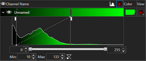
You will see the expanded LUT if you have either the Maximum Projection or Composite Volume rendering mode selected. An intensity histogram is shown indicating the frequency of each intensity level.
The expanded LUT mode gives you finer control over the minimum and maximum dynamic range values. You can double-click on the dotted line to add another LUT Adjustment Point, which can be clicked and dragged for tuning of the LUT.
ISO level
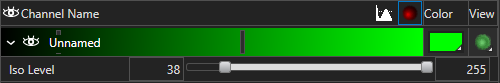
The ISO level display is shown when you have the Preview Surface rendering mode selected. The ISO Level sliders and textboxes let you specify the minimum and maximum intensity levels for mesh generation. This is the main control for adjusting the display in Preview Surface mode.